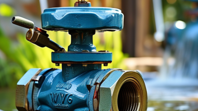
Water systems are expected to deliver steady pressure, clean flow, and dependable service every day. Yet trapped air can quietly undermine all three. Air pockets may collect at high points, narrow the effective flow area, increase head loss, and create unstable pressure. In severe cases, sudden air movement can contribute to water hammer and pipeline stress.
An air release valve provides a controlled outlet for accumulated air during normal operation. This function can protect pumps, improve hydraulic stability, and reduce avoidable maintenance. The need is increasingly relevant as utilities manage aging networks. The U.S. Environmental Protection Agency’s 2023 Seventh Drinking Water Infrastructure Needs Survey and Assessment estimates $625 billion in drinking water investment needs from 2021 to 2041. The American Society of Civil Engineers rated U.S. drinking water infrastructure C− in its 2021 Infrastructure Report Card. These reports do not make valves a universal solution. They do show why small protective components deserve careful attention.
A properly selected air release valve should match pipeline pressure, water quality, flow conditions, and installation elevation. AWWA Manual M51 provides recognized guidance on air-release, air/vacuum, and combination air valves. Field engineers also examine valve sizing, discharge safety, maintenance access, and surge behavior. Details matter. A poorly positioned valve may release too little air, while an undersized model can leave a visible pressure problem unresolved. A valve is not a cure-all. However, when supported by sound hydraulic design and routine inspection, it can help water systems operate more smoothly, safely, and efficiently. The best choice begins with measured conditions, not assumptions.
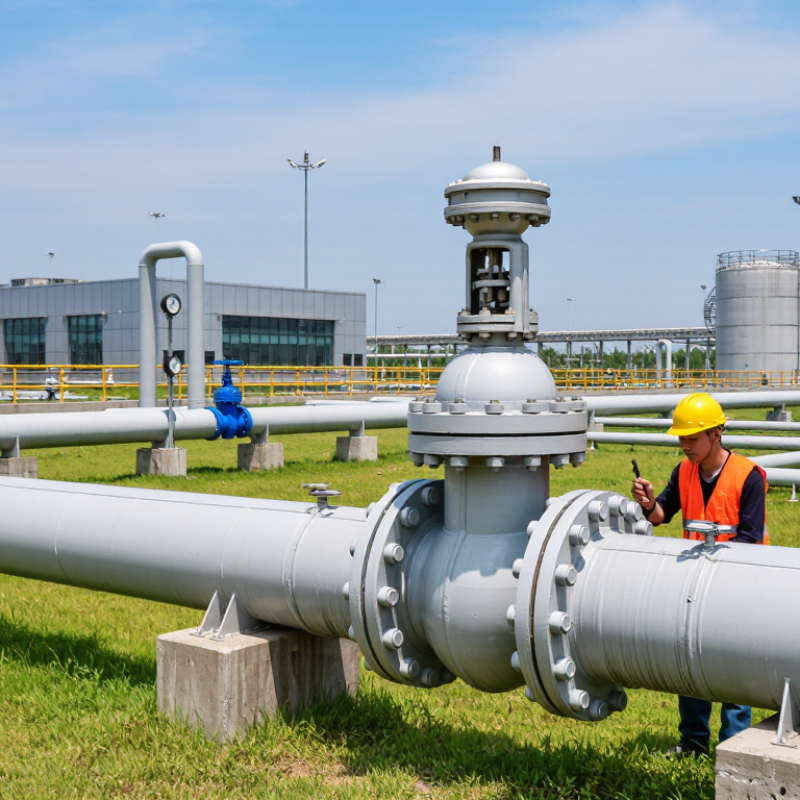
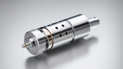
An air release valve is a mechanical device that removes trapped air from pressurized water pipelines. Air gathers at high points, bends, and sections where the pipe rises. It can reduce flow, create noisy operation, and increase pressure fluctuations. The valve gives this air a controlled escape path.
Inside the valve, a float usually moves with the water level. When air fills the chamber, the float drops and opens a small outlet. Water then lifts the float, closing the outlet during normal operation. The principle is simple. The conditions are not. Pressure, pipe size, water quality, and air volume affect valve performance.
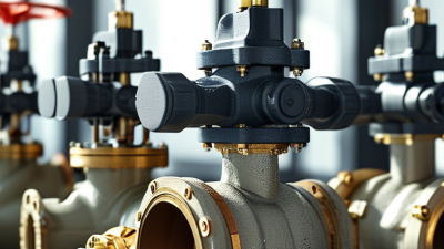
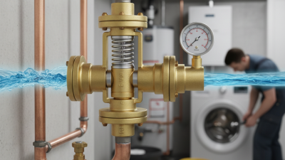
In field inspections, technicians often find these valves near pump discharge lines and pipeline summits. Correct positioning matters because a valve installed below an air pocket may not remove it effectively. A standard air release valve handles accumulated air during normal operation. It may not admit enough air during draining or protect against sudden vacuum conditions; a combination design may be required. That distinction is easy to miss. Sediment and corrosion can also prevent the float from sealing completely. Regular inspection should check the outlet, isolation fitting, and internal movement. Designers should verify operating data rather than rely on a familiar pipe arrangement. Mistakes happen. The pipeline usually reveals them through vibration, uneven flow, or repeated maintenance calls.
| Data Dimension | Typical Information | Technical Data or Condition | Importance in a Water System |
|---|---|---|---|
| Definition | An air release valve is an automatic valve that discharges accumulated air from a pressurized water pipeline. | Normally installed at high points and other locations where air can collect. | Helps maintain the intended flow area and reduces air-related operating problems. |
| Primary Function | Continuous release of small quantities of air while the pipeline remains under pressure. | Uses a float-operated mechanism that opens when air lowers the water level inside the valve chamber. | Prevents air pockets from restricting flow and increasing pumping energy. |
| Air Released | Entrained or accumulated air introduced during filling, maintenance, leakage, or normal operation. | Small, continuous air volumes rather than large quantities of air during filling or draining. | Supports stable hydraulic performance and reduces the likelihood of air binding. |
| Typical Installation Point | Local high points, long ascending pipe sections, changes in pipeline gradient, and upstream sides of control devices. | Installed on a vertical branch or service connection at the highest practical point. | Correct positioning is essential because air naturally migrates toward high points. |
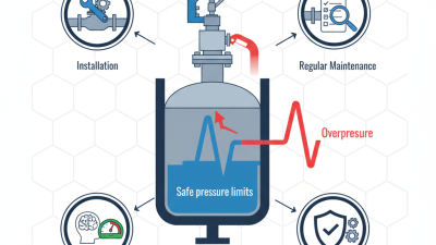
| Operating Pressure | Selected according to the pipeline’s normal and maximum working pressure. | Common water-system ratings include approximately 10, 16, or 25 bar, but the actual rating must match the system design. | Prevents leakage, deformation, or failure caused by an unsuitable pressure class. |
| Nominal Connection Size | The connection size determines how the valve is attached to the pipeline or branch assembly. | Small air release valves commonly use threaded connections from about DN15 to DN50; larger combination valves may use flanged sizes from about DN50 upward. | The size should be selected from air-volume calculations, not only from the main-pipe diameter. |
| Valve Mechanism | Float-operated automatic closure and opening. | The float rises with incoming water to close the outlet and falls when accumulated air displaces water. | Allows automatic operation without electrical power or manual intervention. |
| Valve Body Materials | Materials are chosen for pressure, corrosion resistance, water quality, and temperature. | Common options include ductile iron, cast iron, stainless steel, engineering plastics, and corrosion-resistant elastomers. | Material compatibility affects service life, sealing reliability, and suitability for potable water. |
| Flow Restriction | Accumulated air can reduce the effective cross-sectional area of a pipe. | The resulting pressure loss varies with pipe geometry, air-pocket size, flow velocity, and pipeline slope. | Removing air helps the system operate closer to its designed hydraulic capacity. |
| Energy Consumption | The valve itself generally requires no external electrical power. | Reduced air accumulation can lower unnecessary head loss and associated pump demand. | Improves operational efficiency, especially in long transmission and distribution pipelines. |
| Water Hammer Consideration | Air management influences transient pressure behavior during filling, draining, and flow changes. | A standard small-orifice air release valve is not a complete substitute for a valve designed for large-volume air admission and expulsion. | Correct valve selection helps reduce, but does not automatically eliminate, surge risks. |
| Difference from an Air/Vacuum Valve | An air release valve removes small amounts of air under normal pressurized operation. | An air/vacuum valve admits and expels large air volumes during pipeline filling, draining, or vacuum conditions. | The two functions should not be confused when designing pipeline protection. |
| Difference from a Combination Valve | A combination air valve integrates continuous air release with large-volume air admission and expulsion. | Often selected where a pipeline requires both normal-operation air release and transient protection. | Provides broader air-management capability in one valve assembly. |
| Maintenance Requirements | Periodic inspection and cleaning of the float, seat, screen, and isolation arrangement. | Inspection frequency depends on water quality, sediment level, operating cycles, and manufacturer instructions. | Prevents clogging, continuous leakage, and loss of automatic air-release performance. |
| Selection Criteria | Pipeline profile, air-release demand, pressure range, flow conditions, water quality, connection size, and material compatibility. | Sizing should be based on hydraulic and transient analysis where air accumulation or surge is significant. | Proper selection improves reliability and avoids oversizing, undersizing, or using the wrong valve type. |
| Best Applications | Municipal water networks, pumping stations, irrigation systems, process-water lines, and long-distance pipelines. | Especially useful where pipelines contain high points or operate with frequent filling and flow changes. | Provides a simple, passive method for improving air management across many water applications. |
Note: Pressure ratings, connection sizes, materials, and air-flow capacity are typical engineering ranges. Final selection should be verified against the pipeline profile, design pressure, water quality, applicable standards, and hydraulic calculations.